
The first 3D printed sand mold I unpacked looked wrong. The layer lines were visible, the surface felt rougher than a rammed mold, and I spent ten minutes checking the dimensional prints before I trusted it enough to pour. That gray iron casting came out cleaner than anything I’d made with the same pattern in wood. 3D printing doesn’t replace sand casting — it fits inside it, at specific points in the workflow where traditional pattern tooling is either too slow, too expensive, or geometrically impossible. For a sourcing engineer, the question is never “3D printing or casting” — it’s which mold-making route feeds your sand casting program at the lowest total cost.
3D Printed Sand Molds
Binder jetting prints sand molds directly from a CAD file — no pattern, no core box, no flask work. A print head deposits a binder (furan, phenolic, or inorganic) onto successive layers of foundry sand, building the cope, drag, and any core geometries as a single digital-to-mold workflow. Once printed, you handle them the same way you’d handle any sand mold: assemble, close, pour.
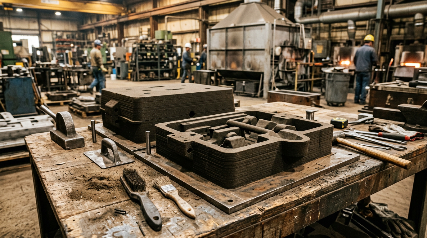
The real advantage shows up in one-off and short-run work. OK Foundry reverse-engineered a 1912 Velie engine block using laser scanning and 3D printed the sand molds and cores. Complex water jacket passages that would have been cost-prohibitive to core traditionally became economically viable for a single casting. They did the same for a historic elevator reel from a Philadelphia building — spiral groove geometry preserved directly in the casting, no machining.
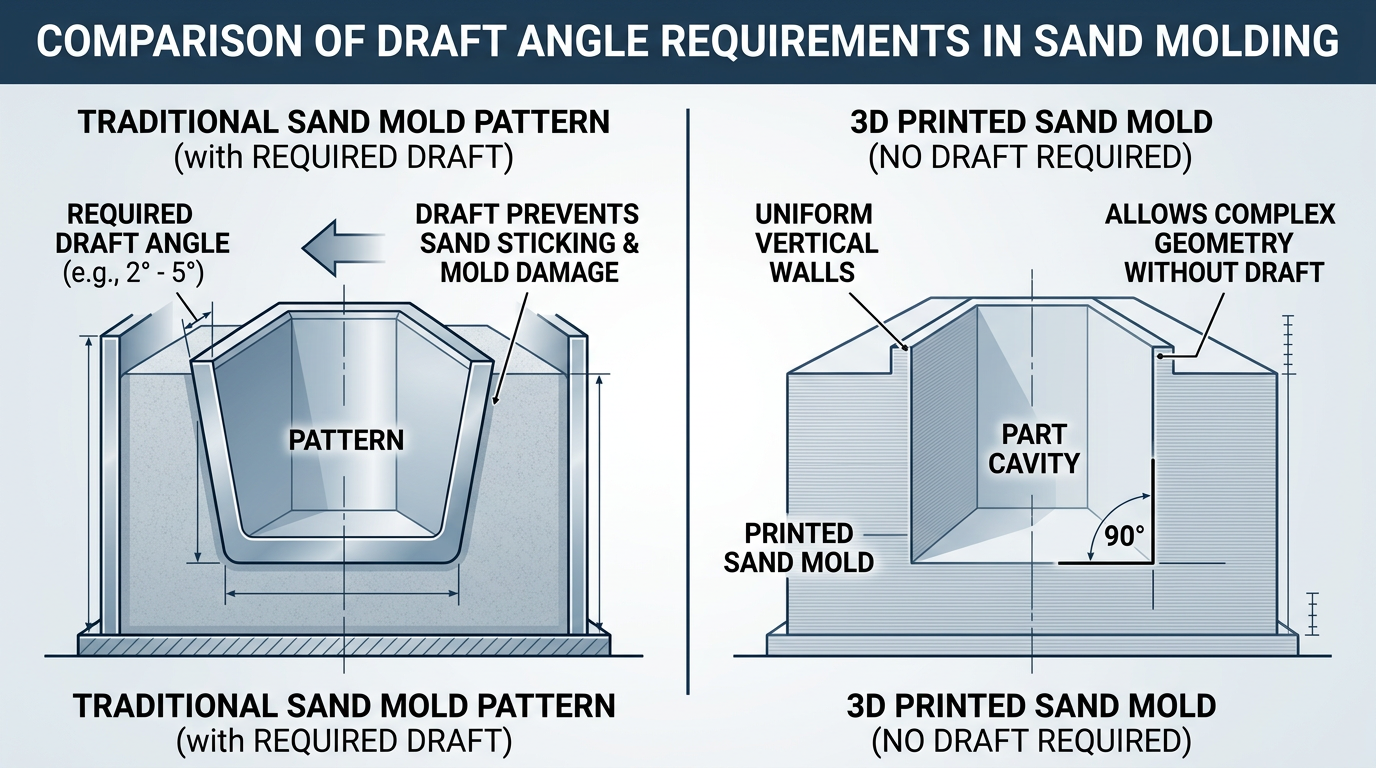
Industrial binder jetting printers hold tolerances of +/-0.3 mm, which is tighter than most hand-rammed molds. The bigger design win is zero draft angle. Traditional patterns need 1-5 degrees of draft for extraction from the sand. Printed molds don’t — the pattern is never physically removed. That means tighter-to-net-shape castings and less machining allowance on finished surfaces.
Before you pour, check the printed mold the same way you’d check any mold. Your binder choice affects the casting as much as the sand — for ferrous pours the binder question is decisive:
- Furan binders: high-strength molds that handle gray and ductile iron pours reliably
- Phenolic systems: better dimensional stability at steel pouring temperatures above 1550 degrees C — the default for carbon and stainless steel
- Inorganic binders: eliminate harmful gas emissions during casting, increasingly a compliance requirement
3D Printed Cores
Liberty Pattern had an aerospace casting that traditionally required assembling over 20 individual core segments. With binder jetting, they printed the entire core as one piece — eliminating assembly labor and every dimensional error that accumulates at each core joint.
Think about what that means on the shop floor. Every time you glue two core segments together, you introduce a potential shift, a flash line, and a defect interface. Multiply that by 20 joints and you’re managing tolerance stack-up across the entire internal geometry. One printed core has zero joints.
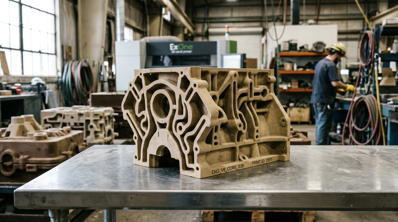
This applies most to castings with complex internal passages — water jackets, oil galleries, manifold runners. If your core design currently requires multi-piece assembly with core prints at each joint, 3D printing can cut your core scrap rate by reducing those joint interfaces to zero. For simple, single-piece cores that you can blow in a core box in 30 seconds, the economics don’t favor printing.
3D Printed Patterns for Sand Casting
3D printing also works one step upstream — printing the pattern itself instead of machining it from wood or urethane board. SLA and SLS printed patterns fill a specific niche: complex geometries at prototype volumes where a pattern shop’s lead time can’t be justified. The printed pattern is used exactly like a wood one — pressed into sand, extracted, and the mold poured.
The limits arrive fast. Printed patterns wear faster than urethane or metal tooling, hold up for far fewer mold cycles, and build-volume ceilings force splitting larger patterns into glued segments — every joint a dimensional risk. That’s why the 3DP-pattern route belongs to prototypes and first articles, with production programs moving to conventional pattern tooling once the design freezes.
Lead Time and Cost Trade-Offs
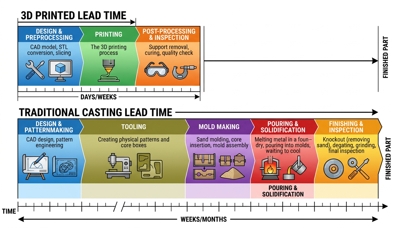
The lead-time case is real. For a prototype ductile iron housing, 3D printed sand molds can deliver first castings in three to five weeks versus the 12-16 weeks a conventional pattern-plus-mold approach would need — the pattern shop simply drops out of the critical path. On complex cored geometries the gap widens further, because printed cores skip core-box tooling entirely.
Cost follows a different curve. 3D sand casting has a near-flat cost curve from one to several hundred parts — the per-unit price barely drops with volume because there’s no tooling to amortize. Traditional casting has high upfront tooling cost but far lower per-unit cost at volume. The crossover depends on part complexity and size, but as a general guide, the break-even against traditional tooling happens around six parts for printed sand cores.
Vendor lead-time savings claims are real, but they apply to prototype and low-volume work. At production volumes above a few hundred parts, traditional tooling costs amortize to pennies per casting while printed mold costs hold steady.
When 3D Printing Doesn’t Make Sense for Casting
High-volume production
If you’re casting 1,000+ identical parts per year, invest in proper patterns and core boxes. The per-unit economics of 3D printing cannot compete with traditional tooling at scale. The cost curve that looks flat at low volumes becomes a ceiling at high volumes, while traditional tooling costs amortize to near zero.
Large castings
Current build volumes on industrial sand printers max out around 31.5 x 15.7 x 19.7 inches. That covers a lot of components, but if you’re pouring machine bases, large valve bodies, or structural frames, you’re back to conventional mold-making. Some printers offer larger build envelopes, but the equipment cost puts them out of reach for most foundries.
Simple geometries
A rectangular housing with no internal passages doesn’t benefit from the geometric freedom of 3D printing. A pattern maker can produce a wood or metal pattern for simple shapes faster and cheaper than the turnaround time on a 3D printing service bureau. The technology pays for itself in complexity — without complexity, you’re paying a premium for convenience.
The right question isn’t whether to use 3D printing for casting. It’s where in your specific workflow the technology removes a bottleneck. For prototypes, complex cores, and legacy part reproduction, it eliminates weeks of lead time and thousands in tooling cost. For production runs, your patterns and core boxes remain the better tool.
When to Choose 3D Printed Molds vs Traditional Pattern Tooling
| Choose 3D printed sand molds/cores when | Choose traditional pattern + sand casting when |
|---|---|
| Prototype or first-article, under ~10 pieces | Production program at any real volume — tooling amortizes, piece price drops |
| Internal geometry needs a 20-segment core consolidated to one | Cores are simple enough to blow in a core box |
| No pattern exists (legacy/obsolete part reproduction) | The design is frozen and will repeat |
| Part fits inside printer build volume (~800 x 400 x 500 mm) | Machine bases, large valve bodies, structural frames |
| Design is still iterating — zero draft lets you test net-shape ideas | Dimensional repeatability across hundreds of molds matters |
Matching the Method to the Job
Three applications justify 3D printing in a foundry workflow: prototyping where lead time outweighs per-unit cost, complex cores where consolidation eliminates assembly and improves dimensional accuracy, and legacy reproduction where no pattern exists and only one or two castings are needed. Everything else still belongs to traditional tooling. The one shift I didn’t expect — teams that started with 3D printed prototyping molds now redesign production castings to exploit zero draft angles and consolidated cores, even after switching back to traditional tooling for the run. The printed mold is a design tool, not just a manufacturing shortcut.
For the production side of that equation, a foundry that builds its own pattern tooling and pours ductile iron and carbon steel with in-house CNC machining can take a printed-mold prototype and translate it into production tooling in one DFM review — which is exactly the handoff where most 3DP prototypes stall.