
A simple gray iron casting with no cores ships in four to six weeks. Add multiple cores, and that same part stretches to 16 weeks. That gap is not a vague “complexity surcharge.” It traces to specific design features, each adding time through a different mechanism in the production chain.
Core count, wall thickness variation, tolerance grade, and parting line geometry each independently extend your timeline through different phases — pattern engineering, mold assembly, pour trials, and inspection. Among the factors that influence sand casting lead times, complexity is the one you control at the drawing board.
Core Count and Undercuts
Core count is the single biggest complexity-to-time driver in sand casting. Each core adds time in three phases: core box fabrication, core production, and mold assembly.
A no-core part needs a cope-and-drag pattern and straightforward molding. Add one internal passage and you need a core box, a separate core production step, and a core-setting operation before closing the mold. Add three or four cores with tight register tolerances, and you have introduced a sub-assembly process inside the mold itself.
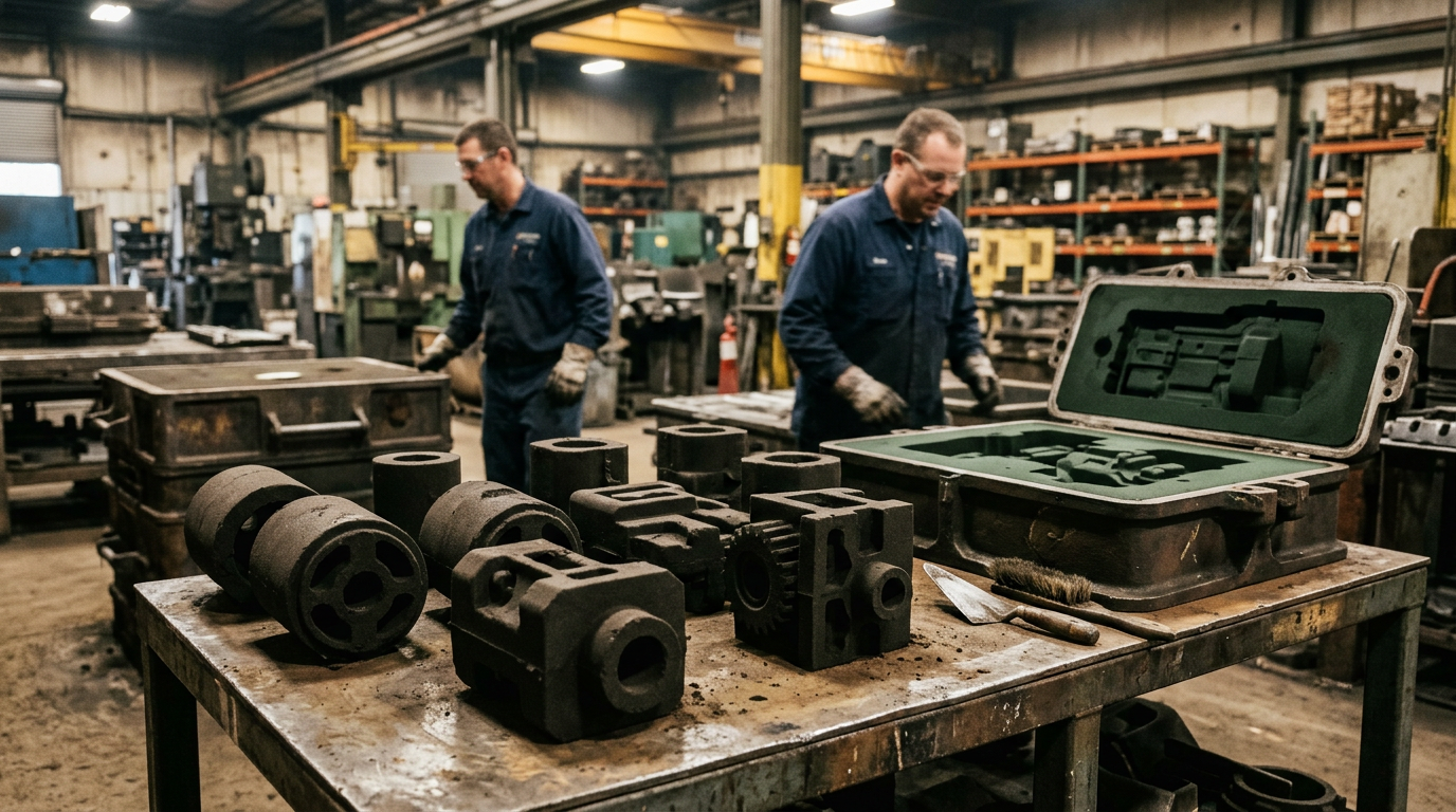
Why Undercuts Multiply Core Requirements
Every undercut that cannot be released from the pattern requires either a loose piece or an additional core. Loose pieces are manual — a molder places them by hand, pours around them, and removes them after shakeout. Each one adds cycle time per casting, not just upfront tooling time.
Before you pour, check whether undercuts can be eliminated by adjusting the parting line. Moving the parting line even a few millimeters can convert a loose-piece situation into a clean draw. I have seen engineers add three cores to a housing because they locked in the parting line based on machining datums without considering moldability. One conversation with the pattern shop saved four weeks.
Estimating Core Impact on Timeline
| Core Scenario | Typical Lead Time Impact |
|---|---|
| No cores (simple cope/drag) | Baseline: 4-6 weeks |
| 1-2 simple cores | +1-2 weeks (core box fabrication + assembly) |
| 3-5 cores with register tolerances | +3-5 weeks (sub-assembly complexity) |
| Multi-core with internal passages | +6-10 weeks (iterative trial pours likely) |
The time compounds when cores interact — two cores sharing a register surface require tighter dimensional control than two independent cores, adding pattern shop hours.
Wall Thickness Variation
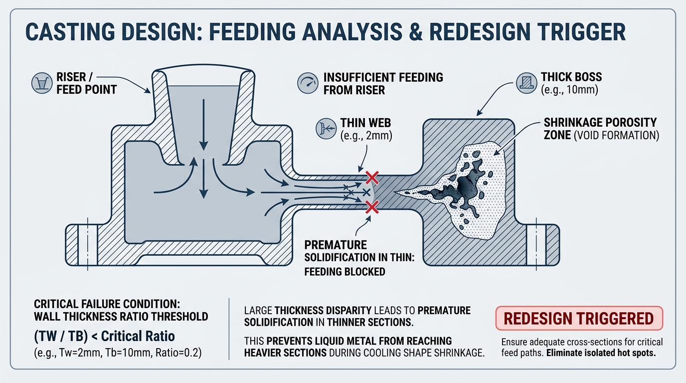
Non-uniform wall sections don’t just create defect risk — they add engineering time to design the feeding system that prevents those defects.
The 2:1 Thickness Ratio Threshold
When your thickest section exceeds twice the thinnest, you have crossed a critical complexity threshold. Past 2:1, the foundry faces two choices: split the part into separate castings joined after machining, or design wedge transitions with a maximum taper of 1:4. Both add engineering time and likely require trial pours to validate.
I have pulled risering designs where the engineer specified a 6 mm web connecting to a 25 mm boss — over 4:1 ratio. The thin web freezes first, cutting off the feeding path to the boss, and you get shrinkage porosity every time. Fixing that part required three riser redesigns and two trial pours before production started.
Hidden Junctions
The problem gets worse when functionally unrelated features occupy the same region. A boss on the outside wall and a rib on the inside create an unintended thick section where they overlap. These hidden junctions are invisible in CAD review but show up as shrinkage cavities on the first casting.
Isolated thick sections cool last and cannot feed from already-solidified surrounding material. The fix — engineering a feeding path from riser to isolated section — adds days to pattern design. Separate functionally unrelated features spatially, or expect additional engineering iterations.
Tolerances and Dimensional Stacking
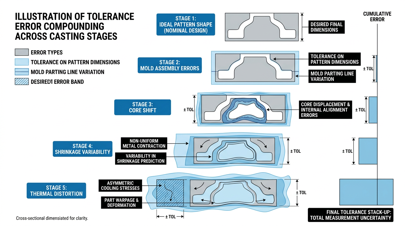
Tight tolerances on a simple part add modest inspection time. Tight tolerances on a complex part create multiplicative error stacking that can consume weeks in iteration cycles.
How Errors Compound on Complex Geometry
A pattern off by just 0.5% does not produce a casting that is 0.5% out of spec. That error compounds with mold assembly variation, core shift, carbon steel’s higher shrinkage over gray iron, and thermal distortion during cooling. On an A216 WCB valve body with cored passages and seat pockets, that error stacks until the bores no longer clean up. The tolerances are individually achievable — the stacking across interacting features is not.
Complex parts with tight tolerances need iterative first-article cycles — pour, measure, adjust pattern, pour again. A straightforward casting might first-article in one cycle. A complex casting with CT7-CT8 requirements on interacting features can consume three to five iterations, each taking one to two weeks.
Machining Allowances as a Time Buffer
Standard machining allowances range from 3/16 inch to 3/4 inch depending on the feature. The most common mistake I see in new patterns is specifying as-cast tolerances that could easily be achieved with a machining allowance instead. Every tolerance shifted from as-cast to as-machined removes a variable from the stacking chain.
If your foundry handles CNC machining in-house, that coordination happens within one facility — eliminating the handoff delay that typically adds one to two weeks when tolerances require post-cast machining.
Gating, Risering, and Parting Line Complexity
Roughly 90% of casting defects trace to gating and feeding system design, not manufacturing execution. Part complexity directly multiplies gating engineering time because each added feature needs its own feeding strategy.
A simple rectangular housing might use a single side gate and one riser. A multi-cored housing with variable wall thickness needs branching runners, multiple risers sized for different sections, and vents positioned to prevent gas entrapment in every core cavity. When gating is wrong on a complex part, each defect requires a design revision and another trial pour. Two to three gating iterations is common on complex castings before production-ready quality is achieved.
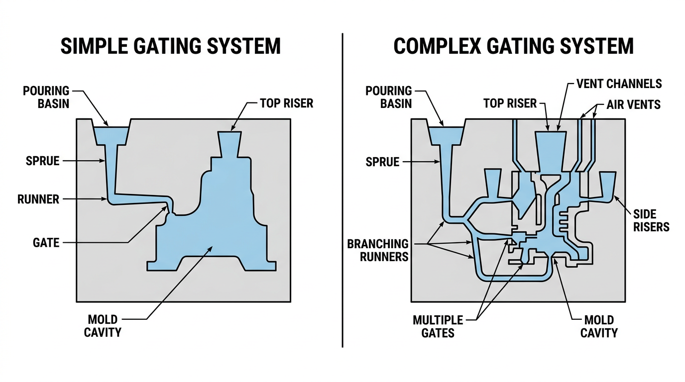
The foundry production schedule allocates specific time blocks for pattern proving and trial pours. Complex parts routinely consume the entire proving allocation.
Draft Angles and Parting Line Placement
Standard draft is 2 degrees, but feature depth changes the equation. Longer features require 3 to 5 degrees to release cleanly. Dry sand molds permit shallower angles (down to 1 degree) due to higher mold strength, but green sand demands the full draft or you risk mold damage during pattern withdrawal.
Parting line placement interacts with every other complexity feature. A poorly chosen parting line forces undercuts requiring loose pieces, creates flash in critical areas (flash must stay under 0.020 inches), and adds cleanup operations. The most effective DFM move I have seen is getting the foundry involved in parting line selection before the design is finalized — that single decision cascades through core requirements, draft angles, and machining datums.
DFM Trade-Offs That Save Schedule Weeks
Every complexity feature above is a design decision. The window for changing those decisions closes once the pattern shop starts cutting.
Three changes consistently deliver the biggest schedule reductions:
- Reduce core count by one. If an internal passage can be achieved through post-cast drilling rather than a core, the total time is almost always shorter.
- Relax one tolerance grade. Moving from CT7 to CT8 (or from as-cast to as-machined) reduces first-article iterations. The machining cost is usually less than the delay cost of additional trial pours.
- Unify wall thickness. Bringing your ratio below 2:1 eliminates complex feeding system design and validation pours.
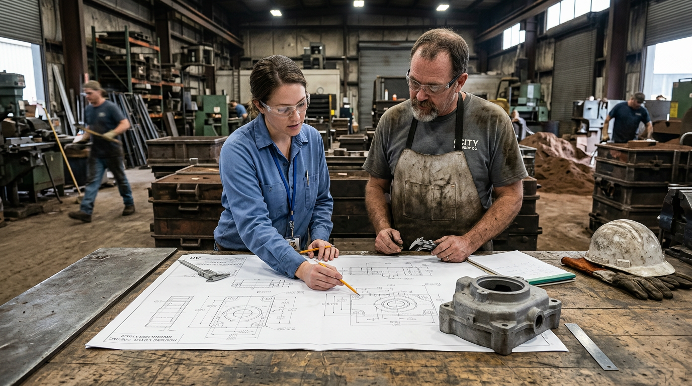
Early DFM collaboration can reduce project delays by addressing complexity before it becomes embedded in tooling. The ideal moment is after preliminary design but before tolerancing is finalized. For low-volume runs under 30 units, 3D sand printing decouples complexity from tooling time entirely — PSSI demonstrated a 60% reduction, from seven weeks to two and a half. Above 30-50 units, traditional tooling remains more economical.
Complexity Checklist for Your Next RFQ
Before submitting a casting RFQ, run through these five questions:
- Core count: Can any internal feature be achieved through post-cast machining instead of a core? Every core eliminated saves one to two weeks.
- Wall ratio: Does your thickest-to-thinnest section exceed 2:1? If yes, expect additional engineering time for feeding system design.
- Tolerance stacking: Are tight tolerances specified on features that interact across cores or parting lines? Shift what you can to as-machined.
- Parting line: Has the foundry reviewed your parting line for core and undercut implications?
- Gating complexity: Does your geometry require branching runners and multiple risers? Budget for two to three trial pour iterations.
The engineers who consistently hit their project timelines are not the ones with the simplest parts. They identify which complexity features drive time and address them before the pattern shop quote arrives.